November 7, 2019
Polygons Everywhere! (Part I)
—A look at data structures for 3-dimensional models.
One aspect of my current position involves working with 3D models. I’m curious about the data structures used to model 3D objects and why polygons and triangles are used in these models. 1
The first representation was developed in 1972 by Bruce G. Baumgart: Winged-edge Polyhedron Representation. It includes a body, face, edge and vertex polyhedron for modelling objects.
A polyhedron:
A “polyhedron” in algebraic topology is defined as a space that can be built from “building blocks” such as line segments, triangles, tetrahedra, and their higher dimensional analogs by “gluing them together” along their faces.
The paper describes a way of mapping between the “real world” and the “model world”. The interface between these worlds is a camera that constructs a 2-dimensional image of the 3-dimensional world it views.
This article walks through Part I of the Winged-edge Polyhedron Representation. The diagrams below are from the original paper.
The Model World
The model world is made of addressable content (essentially computer memory). It comprises:
- topological data which includes the notion of neighbourhood. The face, edge and vertex are essentially part of surface topology. Volume topology is computed. (Topology refers to the geometric surface characteristics of a 3D object.)
- geometric data which includes the notion of locus, length, area and volume. (A locus is a set of all points (e.g., a line, a line segment, a curve or surface), whose location satisfies or is determined by one or more conditions.)
- photometric data which includes the notion of locus, light source and data on light absorbed, reflected, or refracted from the surface.
- parts tree data which descibes the notion that object are composed of parts in the physical world (and not how the entity is broken into parts).
Addressing mechanisms via access requirements.
- appearance uses camera coodinates to show what the world looks like through that camera.
- recognition return model world objects that are present in the image.
- camera solution use image coordinates to determine camera coodinates in real world.
- perception use camera solution to place bodies in image that are not yet recognized.
- spatial accessing given a locus and radius return portion of objects in that sphere.
Camera Model
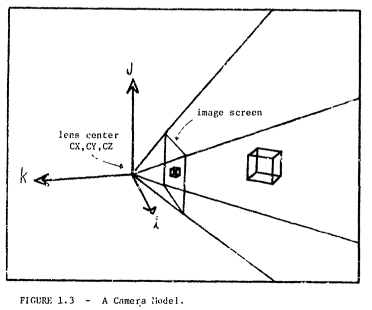
The Real World
Real-world coordinates:
- Camera lens centre: \(CX\), \(CY\) and \(CZ\).
- Camera frame of reference: with unit vectors \(I\), \(J\), \(K\) form a right-handed coordinate system.
- Rotation matrix:
\[\begin{array}{cc}
IX & IY & IZ \\
JX & JY & JZ \\
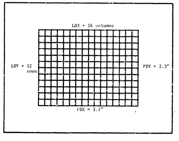
KX & KY & KZ \end{array} \] - Scales determining correspondence between real-world and image size.
- Logical raster size: \(LDX\), \(LDY\) and \(LDZ\). The integer LDZ is an artifact so the units come out correctly in the Z dimension.
-
Physical raster size: \(PDX\), \(PDY\) and \(FOCAL\), where \(FOCAL\) is the focal plane distance. In this model, the focal plane distance is equated with the lens focal length. 2
\(SCALEX \leftarrow -FOCAL \times \frac{LDX}{PDX}\) \(SCALEY \leftarrow -FOCAL \times \frac{LDY}{PDY}\) \(SCALEZ \leftarrow FOCAL \times LDZ\)
Body, Face, Edge and Vertex (BFEV) Modelling
Vertex
A vertex is a point in Euclidean space. It has world locus and world-coordinates \((XWC, YWC, ZWC).\) They are the basic data from which area, volume, face vectors and image positions are calculated.
A vertex may exist simultaneously in multiple image spaces.
An image space with perspective-projected coordinates \((XPP, YPP, ZPP)\). Perspective-projected coordinates are always 3-dimensional and determined with respect to a given camera-centred coordinate system \((XCC, YCC, ZCC)\). The perspective-projected frame is right handed.
The tranformation of a vertex world locus to a camera centred locus is as follows.
-
Translation to the camera frame’s origin: \[\begin{array}{ccc} X & \leftarrow & XWC - CX \\
Y & \leftarrow & YWC - CY \\
Z & \leftarrow & ZWC - CZ \end{array} \] -
Rotation to the camera frame’s origin: \[\begin{array}{ccc} XCC & \leftarrow & IX \times X + IY \times Y + IZ \times Z \\
YCC & \leftarrow & JX \times X + JY \times Y + JZ \times Z \\
ZCC & \leftarrow & KX \times X + KY \times Y + KZ \times Z \\
\end{array} \] -
Perspective projection transformation. \[\begin{array}{ccc} XPP & \leftarrow & SCALEX \times \frac{XCC}{ZCC} \\
YPP & \leftarrow & SCALEY \times \frac{YCC}{ZCC} \\
ZPP & \leftarrow & \frac{SCALEZ}{ZCC} \end{array} \]\(XPP\) and \(YPP\) are derived by means of similar triangles.
\(ZPP\) is always taken inversely proportional to the distance of the vertex from the camera image plane \(ZCC\). It preserves depth and collinearity of the world in the perspective-projected image space.
Vertices in front of the camera’s image plane have negative \(ZPP\). \(ZPP\) values near \(-FOCAL\) are close to the camera; those near zero are far away.
The valence of a vertex is the number of edges that meet at a vertex.
Edge
An edge can be thought of as two vertices. These edges define the 2-dimensional line coefficients.
\[\begin{array}{cc}
AA & \leftarrow & Y1 - Y2 \\
BB & \leftarrow & X2 - X1 \\
CC & \leftarrow & X1 \times Y2 - X2 \times Y1
\end{array}
\]
The coefficients appear in the 2-dimensional equation of the line containing the edge: \(0 = AA \times X + BB \times Y + CC\).
When the edge coefficents are normalized:
\[\begin{array}{cc}
L & \leftarrow & \sqrt{AA + 2 + BB + 2} \\
AA & \leftarrow & \frac{AA}{L} \\
BB & \leftarrow & \frac{BB}{L} \\
CC & \leftarrow & \frac{CC}{L}
\end{array}
\]
The distance from the line to a point \((X, Y)\) is \(Q \leftarrow \lvert AA \times X + BB \times Y + CC \rvert\).
Determining if two edges intersect:
- First, check if the end points of one edge are in the opposite half planes of the other edge.
- Second, check if the end points of the latter edge are in the opposite half planes of the first edge.
If both conditions are true then:
\[\begin{array}{cc}
T & \leftarrow & (A1 \times B2 - A2 \times B1) \\
X & \leftarrow & \frac{(B1 \times C2 - B2 \times C1)}{T} \\
Y & \leftarrow & \frac{(A2 \times C1 - A1 \times C2)}{T}
\end{array}
\]
Check for the identity case.
Check for edges with a common vertex.
Face
A face is a finite region of plane enclosed by straight lines. Faces have characteristice coeeficients: \(AA \times A + BB \times Y + CC \times ZZ = KK\).
\(AA\), \(BB\) and \(CC\) are unit normal vectors. \(KK\) is the distance of the origin from the plane.
The coefficent of a plane can be computed using Cramer’s rule.
3
\[\begin{array}{cc}
KK & \leftarrow & X1 \times (Z2 \times Y3 - Y2 \times Z3) \\
& & + Y1 \times (X2 \times Z3 - Z2 \times X3) \\
& & + Z1 \times (Y2 \times X3 - X2 \times Y3) \\
AA & \leftarrow & (Z1 \times (Y2 - Y3) + Z2 \times (Y3 - Y1) + Z3 \times (Y1 - Y2) \\
BB & \leftarrow & (X1 \times (Z2 - Z3) + X2 \times (Z3 - Z1) + X3 \times (Z1 - Z2) \\
CC & \leftarrow & (X1 \times (Y3 - Y2) + X2 \times (Z3 - Z1) + X3 \times (Y2 - Y1)
\end{array}
\]
Normalized:
\[\begin{array}{cc}
ABC & \sqrt{AA + 2 + BB + 2 + CC + 2} \\
AA & \frac{AA}{ABC} \\
BB & \frac{BB}{ABC} \\
CC & \frac{CC}{ABC} \\
KK & \frac{KK}{ABC}
\end{array}
\]
If vertices \(V1\), \(V2\) and \(V3\) are taken counter clockwise around the exterior of the solid then the relations obtain:
- \(AA \times X + BB \times Y + CC \times Z \le KK\) implies \(X\), \(Y\) and \(Z\) are above the plane.
- \(AA \times X + BB \times Y + CC \times Z = KK\) implies \(X\), \(Y\) and \(Z\) are in the plane.
- \(AA \times X + BB \times Y + CC \times Z \ge KK\) implies \(X\), \(Y\) and \(Z\) are below the plane.
Face coefficents are useful in world and image coordinate systems.
Polyhedra, Bodies and Objects
Simple polyhedra satisfy Euler’s equation \(F - E + V = 2\). A simple polyhedron is one homemorphic to a sphere. Euler’s equation is the primitive basis of the data structure.
A body is an entity more specific than a polyhedron. A polyhedron is represented by the whole structure of bodies, faces, edges and vertices.
A body may have a location, orientation and volume in space. It be connected to faces, edges and vertices which may or may not form a complete polyhedron.
The number of polyhedra associated with a body varies depending upon the object being represented. An object refers to physical objects (e.g., a tree).
A single body is often associated with one polyhedra when representing a rigid object (e.g., a sledge hammer). Several bodies are often associated with one polyhedra when representing a flexible object (e.g., a human being).
The body is also used to represent parts and abstract regional objects (e.g., hierachical composites). For example, a parking lot comprises isles, lanes and lamp islands. A lamp island comprises a lamp; a lamp has a base and top.
The parts structure is carried in body nodes.
Four Kinds of BFEV Accessing
-
Accessing by name and serial number. Involves retreival using a symbolic name.
-
Parts-Tree Accessing. Occurs between different bodies.
At the top of the world exists a body to which all other bodies are attached. Given a body, a list of sub-parts and it’s supra-part can be accessed.
A supra-part is the whole entity to which a part belongs. The world is its own supra-part.
-
FEV Sequence Accessing.
Each body provides sequential accessing to each face, edge and vertex. Sequential access is required because
- perpsective projection loops through every vertex.
- display clipping loops through all edges.
- body intersection loops through all faces.
-
FEV Perimeter Accessing.
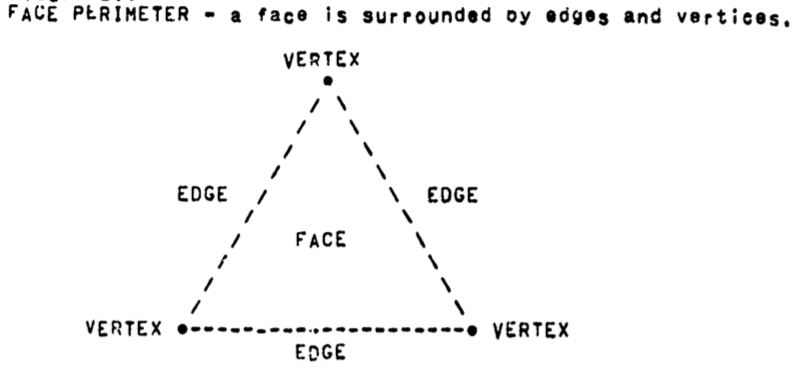
Perimeter accessing requires that given a face, edge or vertex the perimeter of that entity be readily accessible:
-
faces have a perimeter of edges and vertices.
-
-
edges have a perimeter of two faces and two vertices.
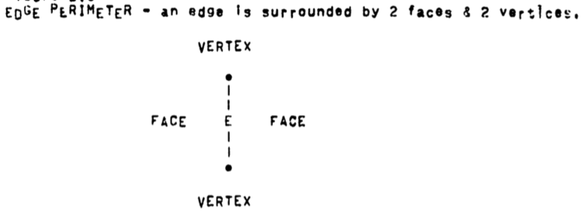
-
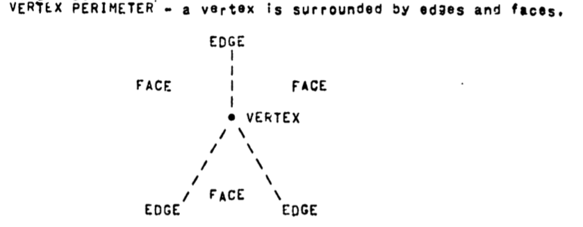
vertices have a perimeter of edges and faces.
The surface of a polyhedron is orientable (has a well defined inside and outside). This means perimeter lists can be ordered (say clockwise) with respect to the polyhedron’s exterior.
Footnotes
1. The introduction: “It is my current predjudice that polyhedra provide the proper starting point for building a physical world representation.” But are they really triangles? In face, “A safe formal face structure could be built by defining a triangle as three non-colinear vertices and insisting that all faces be triangle interiors.”, but the implementation may be different. ↩
2. Under what circumstances does focal length differ from focal distance? Some hints: Ray Optics. ↩
3. The original document refers to Kramer’s rule. Apparently, a typo. ↩
